
Mesostructured & Mesoporous Hybrids
Subtopics: Amorphous Materials / Polycrystalline Materials / Single Crystal Epitaxy / Pattern Analysis
Amorphous Materials
1. Mesostructured and Mesoporous Ceramics
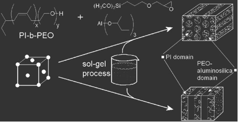
We employ amphiphilic diblock copolymers and triblock terpolymers to structure direct the assembly of precursors for ceramic materials such as aluminosilicate/niobia/titania nanoparticles, as well as oligomeric silazanes.
- Aluminosilicate / PI-b-PEO for mesoporous aluminosilicates
In one example, aluminosilicate nanoparticles are produced in a sol-gel process, where an organically modified silicon alkoxide and an aluminum alkoxide are mixed with water. Slowly drying the solution of nanoparticles and the block copolymer, PI-b-PEO produces well-ordered mesostructures with domains consisting of PI (hydrophobic) and PEO+Aluminosilicate (hydrophilic). By varying the amount of aluminosilicate nanoparticles in the hybrids, a wide range of morphologies can be produced which, in effect, map out the phase diagram of a typical block copolymer.
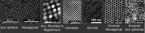
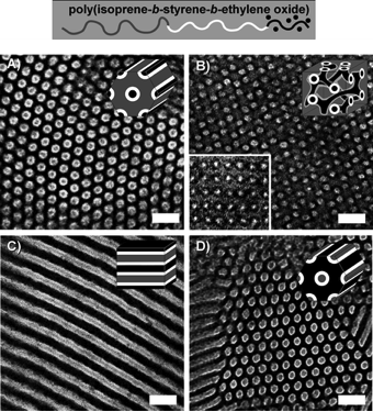
The morphologies typically obtained are (from left to right below) bcc spheres, hexagonally packed cylinders, inverse plumber's nightmare (cubic bicontinuous) lamellae, gyroid, inverse hexagonal cylinders and inverse bcc spheres. These different structures are produced by adding increasing volume fractions of the aluminosilicate-type nanoparticles.
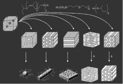
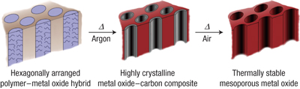
These aluminosilicate-PI-b-PEO hybrids can then either be dissolved to produce "hairy" nano-objects such as spheres, cylinders and lamellae, or heat-treated to burn out the organic material leaving behind mesostructured aluminosilicate ceramic materials. Mesoporous transition metal oxides that have potential applications in energy-harvesting materials have been synthesized in a similar sol-gel route by using PI-b-PEO as structure-directing materials. These materials were crystallized after carbon scaffold, which originated from polyisoprene reinforced the walls of the mesopores, thereby avoiding significant structure collapse (Combined Assemblies of Soft and Hard chemistries, CASH method).
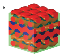
Triblock terpolymers such as poly(isoprene-b-styrene-b-ethylene oxide) have also been used for structure-directing niobia. We find that the phase spaces for 3D network morphologies with triblock terpolymers are larger compared to those of diblock copolymers, giving us more tunability on the hybrid design.
A more exotic four-layer woodpile lattice structure was synthesized via coassembly with a poly(ethylene-co-propylene)-b-(ethylene oxide)-b-(hexyl methacrylate) triblock terpolymer where the middle block is swollen with aluminosilicate nanoparticles.
References:
[2] G. Toombes, S. Mahajan, M. Thomas, P. Du, M. Tate, S. Gruner, U. Wiesner. "Hexagonally-Patterned Lamellar Morphology in ABC Triblock Copolymer/Aluminosilicate Nanocomposites", Chem. Mater. 20 (8), 3278-3287 (2008).
[3] E. Verploegen, B. T. Dworken, M. Faught, M. Kamperman, Y. Zhang, U. Wiesner, "Tuning Mechanical Properties of Block Copolymer-Aluminosilicate Hybrid Materials", Macromol. Rap. Comm. 28, 572-578 (2007).
[4] A. Jain, G. Toombes, L. Hall, S. Mahajan, C. Garcia, W. Probst, S. Gruner, U. Wiesner, "Direct Access to Bicontinuous skeletal Inorganic Plumber�s Nightmare networks from block copolymers", Angew. Chem. Int. Ed. 44, 1226-1229 (2005).
[5] P. Simon, R. Ulrich, H. Spiess, U. Wiesner, "Block Copolymer-Ceramic Hybrid Materials from Organically Modified Ceramic Precursors", Chemistry of Materials 13 (10), 3464-3486 (2001).
[6] A. Jain, U. Wiesner. "Silica-Type Mesostructures from Block Copolymer Phases: Formation Mechanism and Generalization to the Dense Nanoparticle Regime" Macromolecules 37 (15), 5665-5670 (2004).
[7] M. Templin, A. Franck, A. Du Chesne,H. Leist, Y. Zhang, R. Ulrich, V. Schadler, U. Wiesner. "Organically modified aluminosilicate mesostructures from block copolymer phases", Science, 278 (5344), 1795-1798 (1997).
[8] R. Ulrich, A. Du Chesne, M. Templin, U. Wiesner, "Nano-objects with controlled shape, size, and composition from block copolymer mesophases", Advanced Materials 11 (2), 141-146 (1999).
[9] J. Lee, M. Orilall, S. Warren, M. Kamperman, F. DiSalvo, U.Wiesner, "Direct Access to Thermally Stable and Highly Crystalline Mesoporous Transition-Metal Oxides with Uniform Pores". Nat. Mater. 7, 222-228 (2008).
[10] M. Stefik, S. Mahajan, H. Sai, T. Epps, F. Bates, S. M. Gruner, F. DiSalvo, U. Wiesner. "Ordered Three- and Five-ply Nanocomposites from ABC Block Terpolymer Microphase Separation with Niobia and Aluminosilicate Sols", Chem. Mater. 21 (22), 5466-5473 (2009).
[11] M. Stefik, H. Sai, K. Sauer, S. M. Gruner, F. J. DiSalvo, U. Wiesner. "Three-Component Porous-Carbon-Titania Nanocomposites through Self-Assembly of ABCBA Block Terpolymers with Titania Sols", Macromolecules 42 (17), 6682-6687 (2009).
[12] M. Stefik, J. Lee, U. Wiesner. " Nanostructured carbon-crystalline titania composites from microphase separation of poly(ethylene oxide-b-acrylonitrile) and titania sols", Chem. Commun., 2532-2534 (2009).
2. Disassembly of Composite Materials
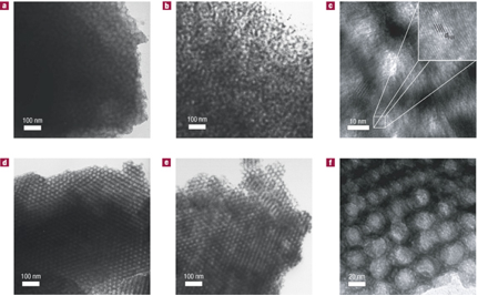
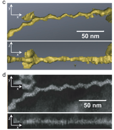
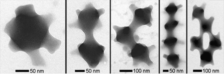
Disassembly of nanoparticle-block copolymer hybrids is also possible, owing to the discrete nature of nanoparticles that make up the hybrids. Application of the retrosynthetic methodology from organic synthesis to mesostructured materials suggests that an inverse hexagonal hybrid can be disassembled into nanotubes, and that an Inverse Plumber's Nightmare hybrid can be disassembled into a variety of structural building units.
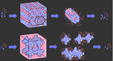
Indeed, a variety of structures can be produced through this disassembly route, as shown a single unit cell (a "monomer"), two unit cells (a "dimer"), and so on as shown schematically above and by TEM below.
References:
3. Nanoparticle-derived Hybrid Materials
Particles larger than the hydrophilic block of the block copolymers segregate into onion cores. If the block copolymer were to mix with the largest particles, the polymer chain would have to elongate in order to mix. This is entropically unfavorable, as the polymer prefers to exist as a coil, a state in which the number of conformations is greater. Instead of taking this entropic penalty, the largest particles segregate into onion cores. Through the control of nanoparticle size and size distribution, unusual morphologies can be produced from nanoparticle-block copolymer hybrids. For example, when small nano-particles are mixed with a block copolymer, a lamellar morphology is produced. When using larger nanoparticles, however, onion-type mesostructures are produced. This same concept allows large nanoparticles with similar surface chemistry but distinct interior compositions to be isolated in the onion core.
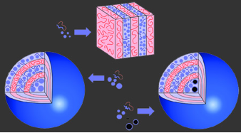
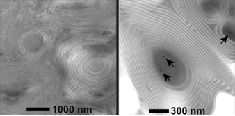
A typical onion-type mesostructure is shown above. Above we also show the localization of gold-silica core-shell nanoparticles in the onion cores through size effects. Because the gold particles are larger than the hydrophilic block, these particles also segregate into the onion cores.
References:
Polycrystalline Materials
1. Ordered Mesoporous High Temperature Ceramics
Non-oxide type ceramics are of particular interest because of their excellent thermal stability and mechanical properties, with potential applications in high-temperature reaction catalyst support. We have expanded on the aluminosilicate structure-directing scheme and developed a procedure to synthesize mesoporous non-oxide ceramics. Heat treatment up to temperatures as high as 1500 C converts the composites into ordered non-oxide type high-temperature ceramics, as shown in the TEM images below.
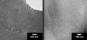
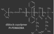
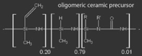
In this case, the ceramic precursor is an oligomer and the composites are formed by crosslinking the oligomers after mixing with the block copolymer.
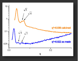
Small-Angle X-Ray Scattering (SAXS) analysis shows that order is maintained for both the as-made and 1500 C-calcined materials.
References:
[1] M. Kamperman, P. Du, R. Scarlat, E. Herz, U. Werner-Zwanziger, R. Graf, J. W. Zwanziger, H. W. Speiss, U. Wiesner "Ordered Mesostructured High Temperature Ceramics using Block Copolymer Mesophases" Macromolecular Chemistry and Physics 208, 2096-2108 (2007).
[2] C. Garcia, C. Lovell, C. Curry, M. Faught, Y. Zhang, U. Wiesner. "Synthesis and characterization of block copolymer/ceramic precursor nanocomposites based on a polysilazane" Journal of Polymer Science, Part B: Polymer Physics 41 (24), 3346-3350 (2003).
[3] M. Kamperman, C. Garcia, P. Du, H. Ow, U. Wiesner. "Ordered Mesoporous Ceramics Stable up to 1500�C from Diblock Copolymer Mesophases", Journal of the American Chemical Society 126 (45), 14708-14709 (2004).
Single Crystal Epitaxy
1. Block Copolymer Self-Assembly-Directed Single-Crystal Epitaxial Structures
Bottom-up self-assembly materials provides an alternative low cost approach to large area nanostructure fabrication and may play an important role to meet important economic and technological goals for more efficient processes, greener energy storage and generation and smaller devices [1]. And in contrast to lithographic techniques, the self-assembly process is highly parallel and inherently allows a more rapid 3D structure formation [2].
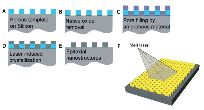
Figure 1
We recently reported combining block copolymer self-assembly directed nanoporous template formation with thermal processing to achieve single-crystal nanostructures with epitaxial relation to a silicon substrate in 10-100 nm thick films [3]. The fabrication process is schematically summarized in the Figure 1. We began with an inverse hexagonally arranged diblock copolymer structure-directed aluminosilicate thin film template. The native oxide layer on the Si substrate was etched away prior to amorphous Si (a-Si) deposition. A clean interface between the a-Si overlayer and Si substrate was the key to achieve single-crystal epitaxial nanostructures. The sample was irradiated with a pulsed XeCl excimer laser (308 nm wavelength) to induce a transient melt and solidification conversion with the molten Si recrystallizing epitaxially from the single-crystal Si substrate. Finally the template was etched away in hydrofluoric acid leaving porous single-crystal epitaxial nanostructures behind.
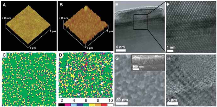
Figure 2
The hexagonal pattern transfer yields of the single-crystal Si homoepitaxial nanopillars were high and long-range order was maintained. Atomic force microscopy (AFM) images and Voronoi analysis in Figure 2 verified a high pattern transfer fidelity of about 90 % from the template (Figure 2A) to silicon (Figure 2B). High resolution transmission electron microscopy (HR-TEM) in Figures 2E and 2F confirmed the single-crystal homoepitaxial nature of the silicon nanopillars to the substrate.
There are numerous advantages to this method. First, the approach is highly flexible and scalable in material selection and dimensions. To this end, we employed a block copolymer directed niobia template to grow a roughly 100 nm thick single-crystal homoepitaxial silicon nanoporous film with a three-dimensionally interconnected pore network structure, see Figures 2G and 2H. Confinement of the interface area to nanoscopic dimensions further allows the growth of heteroepitaxial nanostructures. As an example, we made use of the porous nature of the block copolymer directed aluminosilicate template to laterally control and confine moderately lattice mismatched NiSi on silicon to generate single-crystal heteroepitaxial nanostructures.
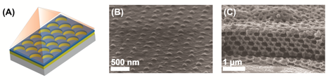
Figure 3
Most recently, we combined colloidal self-assembly-directed templating approach with pulsed laser irradiation to generate crystalline silicon nanostructures with non-close-packed (ncp) symmetry in two- and three-dimensions, see Figure 3 [4].
In summary, our results suggest a general strategy coupling soft-matter self-assembly with laser thermal processing to direct and design intricate complex nanopatterned crystalline inorganic nanomaterials that could be used in advanced applications such as sensors, catalysis, and energy conversion.
References
[1] Baxter, J. et al. Nanoscale design to enable the revolution in renewable energy. Energy Environ. Sci. 2, 559 (2009).
[2] Pease, R.F. & Chou, S.Y. Lithography and Other Patterning Techniques for Future Electronics. Proc. IEEE 96, 248-270 (2008).
[3] Arora, H. et al. Block Copolymer Self-Assembly–Directed Single-Crystal Homo- and Heteroepitaxial Nanostructures. Science 330, 214 -219 (2010).
[4] Tan, K.W., Saba, S.A., Arora, H., Thompson, M.O. & Wiesner, U. Colloidal Self-Assembly-Directed Laser-Induced Non-Close-Packed Crystalline Silicon Nanostructures. ACS Nano, ASAP (2011).
Voronoi and Nearest Neighbor Pattern Analysis Algorithms
We have developed software to analyze the patterns created by block copolymer thin films which can be downloaded here.
Software Overview and Walkthrough
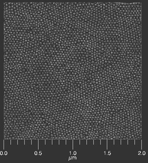
This program will allow you to analyze repetitive pictures in microscopy images. After inputting the image, the program will first determine the pore centers (right) based on the topology (intensity) of the image (AFM in this case, left)
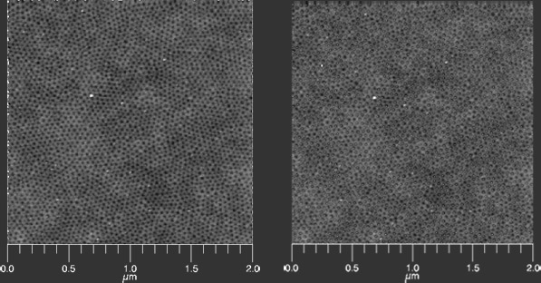
It performs Delaunay triangulation to analyze the triangulation relative positions of neighboring centers with the condition that the circle through the triangle vertices is free from other centers like the black circle in (b) below. This analysis is shown below as performed on the image shown at the top of the page.
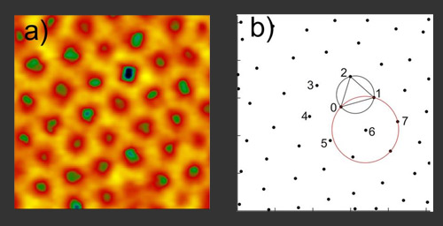
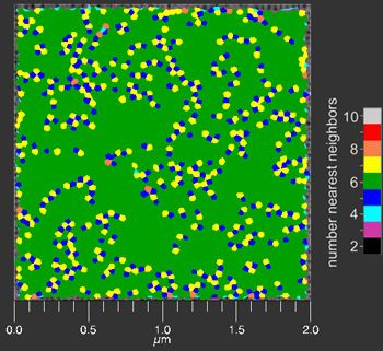
This analysis can be taken further to determine the number of nearest neighbors to each center in a field of interest. This analysis is plotted as a Voronoi diagram: the color-coded n-sided polygon represents a center point having an equivalent n number of nearest neighbors.
Instructions to use IDL watershed program
- Download watershed.zip
- Download and install IDL VM
- Unzip files into the folder, Z:\RSI\IDLXX\IDLXX\watershed folder (where XX is the IDL version stored in Z drive)
- Run IDL VM or IDL
- Write [!PATH = Expand_Path('+Z:\RSI\IDLXX\user_contrib\topo\') + ';' + !PATH] in the command prompt
- Write [.run topostart] in the command prompt
- Open the watershed project by going to IDL toolbar and clicking File -> Open Project -> DI_watershed (IDL project file in watershed folder)
- Ignore any error message that might appear at this point
- Compile all files by clicking Project -> Compile -> All Files
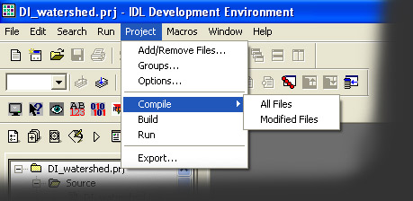
- Then click Project -> Run in the IDL toolbar
- A new window will pop to File -> Open the desired flattened AFM image in binary format.
- Press Calculate after making the appropriate choice of primary and overlay image. For example, use bare SFM as primary image and use centers as overlay to find coordinates of centers in SFM.
- The coordinates are saved as centers.txt in the folder, \RSI\IDLXX\watershed folder